2
| Inputs | Output | |
| \(x\) | \(y\) | \(x \text{ AND } y\) |
| \(1\) | \(1\) | \(1\) |
| \(1\) | \(0\) | \(0\) |
| \(0\) | \(1\) | \(0\) |
| \(0\) | \(0\) | \(0\) |
Model systems with tools from discrete mathematics and reason about implications of modelling choices. Explore applications in CS through multiple perspectives, including software, hardware, and theory.
Determining the properties of positional number representations, including overflow and bit operations
Connecting logical circuits and compound proposition and tracing to calcluate output values
Translate between different representations to illustrate a concept.
Translating between symbolic and English versions of statements using precise mathematical language
Use precise language to clearly present logical arguments and communicate with technical and non-technical colleagues.
Distinguishing between tautologies, contradictions, and contingencies
Use precise notation to encode meaning and present arguments concisely and clearly
Listing the truth tables of atomic boolean functions (and, or, xor, not, if, iff)
Know, select and apply appropriate computing knowledge and problem-solving techniques. Reason about computation and systems. Use mathematical techniques to solve problems. Determine appropriate conceptual tools to apply to new situations. Know when tools do not apply and try different approaches. Critically analyze and evaluate candidate solutions.
Evaluating compound propositions
Judging logical equivalence of compound propositions using symbolic manipulation with known equivalences, including DeMorgan’s Law
Judging logical equivalence of compound propositions using truth tables
Rewriting compound propositions using normal forms
Judging whether a collection of propositions is consistent
Review quiz based on Week 2 class material (extended because signed number representations weren’t covered until Week 3; now due Monday 01/26/2026)
Review quiz based on Week 3 class material (due Monday 01/26/2026)
Fixed-width addition: adding one bit at time, using the usual column-by-column and carry arithmetic, and dropping the carry from the leftmost column so the result is the same width as the summands. Does this give the right value for the sum?
2 \[\begin{align*} & [0~ 1~ 0~ 1]_{s,4}\\ + & [1~ 1~ 0~ 1]_{s,4}\\ &\overline{\phantom{[0~0~1~0]_{s,4}}}\\ \end{align*}\]
\[\begin{align*} & [0~ 1~ 0~ 1]_{2c,4}\\ + & [1~ 0~ 1~ 1]_{2c,4}\\ &\overline{\phantom{[0~0~0~0]_{2c,4}}}\\ \end{align*}\]
3 \[\begin{align*} & (1~ 1~ 0~ 1~ 0~ 0)_{2,6}\\ + & (0~ 0~ 0~ 1~ 0~ 1)_{2,6}\\ &\overline{\phantom{(1~1~1~0~0~1)_{2,6}}}\\ \end{align*}\]
\[\begin{align*} & [1~ 1~ 0~ 1~ 0~ 0]_{s,6}\\ + & [0~ 0~ 0~ 1~ 0~ 1]_{s,6}\\ &\overline{\phantom{(1~1~1~0~0~1)_2}}\\ \end{align*}\]
\[\begin{align*} & [1~ 1~ 0~ 1~ 0~ 0]_{2c,6}\\ + & [0~ 0~ 0~ 1~ 0~ 1]_{2c,6}\\ &\overline{\phantom{(1~1~1~0~0~1)_2}}\\ \end{align*}\]
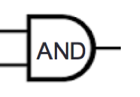
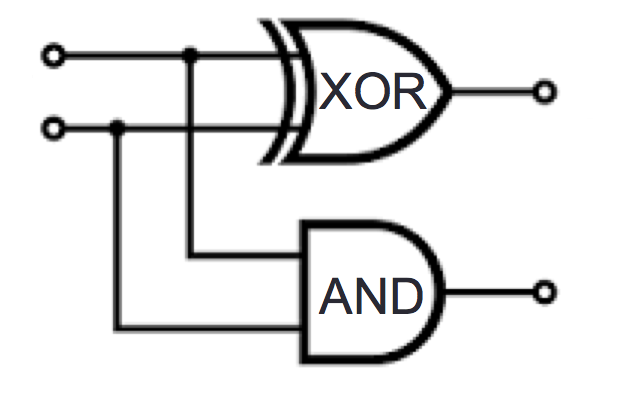
In a combinatorial circuit (also known as a logic circuit), we have logic gates connected by wires. The inputs to the circuits are the values set on the input wires: possible values are 0 (low) or 1 (high). The values flow along the wires from left to right. A wire may be split into two or more wires, indicated with a filled-in circle (representing solder). Values stay the same along a wire. When one or more wires flow into a gate, the output value of that gate is computed from the input values based on the gate’s definition table. Outputs of gates may become inputs to other gates.
2
| Inputs | Output | |
| \(x\) | \(y\) | \(x \text{ AND } y\) |
| \(1\) | \(1\) | \(1\) |
| \(1\) | \(0\) | \(0\) |
| \(0\) | \(1\) | \(0\) |
| \(0\) | \(0\) | \(0\) |
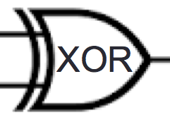
2
| Inputs | Output | |
| \(x\) | \(y\) | \(x \text{ XOR } y\) |
| \(1\) | \(1\) | \(0\) |
| \(1\) | \(0\) | \(1\) |
| \(0\) | \(1\) | \(1\) |
| \(0\) | \(0\) | \(0\) |
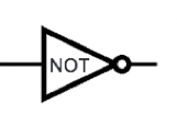
2
| Input | Output |
| \(x\) | \(\text{NOT } x\) |
| \(1\) | \(0\) |
| \(0\) | \(1\) |
Example digital circuit:
2
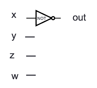
Output when \(x=1, y=0, z=0, w = 1\) is Output when \(x=1, y=1, z=1, w = 1\) is Output when \(x=0, y=0, z=0, w = 1\) is
Draw a logic circuit with inputs \(x\) and \(y\) whose output is always \(0\). Can you use exactly 1 gate?
Fixed-width addition: adding one bit at time, using the usual column-by-column and carry arithmetic, and dropping the carry from the leftmost column so the result is the same width as the summands. In many cases, this gives representation of the correct value for the sum when we interpret the summands in fixed-width binary or in 2s complement.
For single column:
2
| Input | Output | ||
| \(x_0\) | \(y_0\) | \(c_0\) | \(s_0\) |
| \(1\) | \(1\) | ||
| \(1\) | \(0\) | ||
| \(0\) | \(1\) | ||
| \(0\) | \(0\) | ||
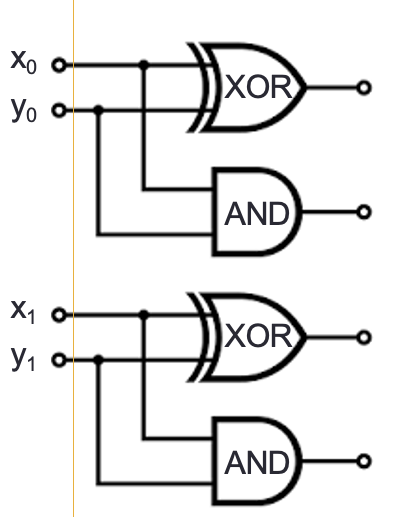
Draw a logic circuit that implements binary addition of two numbers that are each represented in fixed-width binary:
Inputs \(x_0, y_0, x_1, y_1\) represent \((x_1 x_0)_{2,2}\) and \((y_1 y_0)_{2,2}\)
Outputs \(z_0, z_1, z_2\) represent \((z_2 z_1 z_0)_{2,3} = (x_1 x_0)_{2,2} + (y_1 y_0)_{2,2}\) (may require up to width \(3\))
First approach: half-adder for each column, then combine carry from right column with sum of left column
Write expressions for the circuit output values in terms of input values:
\(z_0 = \underline{\phantom{x_0 \oplus y_0\hspace{3in}}}\)
\(z_1 = \underline{\phantom{(x_1 \oplus y_1) \oplus c_0}\hspace{2.5in}}\)
\(z_2 = \underline{\phantom{(c_0 \land (x_1
\oplus y_1)) \oplus c_1}\hspace{2in}}\)
There are other approaches, for example: for middle column, first add carry from right column to \(x_1\), then add result to \(y_1\)
Logical operators aka propositional connectives
| Conjunction | AND | \(\land\) | \land |
2 inputs | Evaluates to \(T\) exactly when both inputs are \(T\) |
| Exclusive or | XOR | \(\oplus\) | \oplus |
2 inputs | Evaluates to \(T\) exactly when exactly one of inputs is \(T\) |
| Disjunction | OR | \(\lor\) | \lor |
2 inputs | Evaluates to \(T\) exactly when at least one of inputs is \(T\) |
| Negation | NOT | \(\lnot\) | \lnot |
1 input | Evaluates to \(T\) exactly when its input is \(F\) |
Truth tables: Input-output tables where we use \(T\) for \(1\) and \(F\) for \(0\).
| Input | Output | |||
| Conjunction | Exclusive or | Disjunction | ||
| \(p\) | \(q\) | \(p \land q\) | \(p \oplus q\) | \(p \lor q\) |
| \(T\) | \(T\) | \(T\) | \(F\) | \(T\) |
| \(T\) | \(F\) | \(F\) | \(T\) | \(T\) |
| \(F\) | \(T\) | \(F\) | \(T\) | \(T\) |
| \(F\) | \(F\) | \(F\) | \(F\) | \(F\) |
|
|
 |
||
| Input | Output |
| Negation | |
| \(p\) | \(\lnot p\) |
| \(T\) | \(F\) |
| \(F\) | \(T\) |
|
| Input | Output | ||||
| \(p\) | \(q\) | \(r\) | \((p \land q) \oplus (~ ( p \oplus q) \land r~)\) | \((p \land q) \vee (~ ( p \oplus q) \land r~)\) | |
| \(T\) | \(T\) | \(T\) | |||
| \(T\) | \(T\) | \(F\) | |||
| \(T\) | \(F\) | \(T\) | |||
| \(T\) | \(F\) | \(F\) | |||
| \(F\) | \(T\) | \(T\) | |||
| \(F\) | \(T\) | \(F\) | |||
| \(F\) | \(F\) | \(T\) | |||
| \(F\) | \(F\) | \(F\) | |||
Given a truth table, how do we find an expression using the input variables and logical operators that has the output values specified in this table?
Application: design a circuit given a desired input-output relationship.
| Input | Output | ||
| \(p\) | \(q\) | \(mystery_1\) | \(mystery_2\) |
| \(T\) | \(T\) | \(T\) | \(F\) |
| \(T\) | \(F\) | \(T\) | \(F\) |
| \(F\) | \(T\) | \(F\) | \(F\) |
| \(F\) | \(F\) | \(T\) | \(T\) |
Expressions that have output \(mystery_1\) are
Expressions that have output \(mystery_2\) are
Idea: To develop an algorithm for translating truth tables to expressions, define a convenient normal form for expressions.
Definition An expression built of variables and logical operators is in disjunctive normal form (DNF) means that it is an OR of ANDs of variables and their negations.
Definition An expression built of variables and logical operators is in conjunctive normal form (CNF) means that it is an AND of ORs of variables and their negations.
Proposition: Declarative sentence that is true or false (not both).
Propositional variable: Variable that represents a proposition.
Compound proposition: New proposition formed from existing propositions (potentially) using logical operators. Note: A propositional variable is one example of a compound proposition.
Truth table: Table with one row for each of the possible combinations of truth values of the input and an additional column that shows the truth value of the result of the operation corresponding to a particular row.
Logical equivalence : Two compound propositions are logically equivalent means that they have the same truth values for all settings of truth values to their propositional variables.
Tautology: A compound proposition that evaluates to true for all settings of truth values to its propositional variables; it is abbreviated \(T\).
Contradiction: A compound proposition that evaluates to false for all settings of truth values to its propositional variables; it is abbreviated \(F\).
Contingency: A compound proposition that is neither a tautology nor a contradiction.
Label each of the following as a tautology, contradiction, or contingency.
\(p \land p\)
\(p \oplus p\)
\(p \lor p\)
\(p \lor \lnot p\)
\(p \land \lnot p\)
Extra Example: Which of the compound propositions in the table below are logically equivalent?
| Input | Output | |||||
| \(p\) | \(q\) | \(\lnot (p \land \lnot q)\) | \(\lnot (\lnot p \lor \lnot q)\) | \((\lnot p \lor q)\) | \((\lnot q \lor \lnot p)\) | \((p \land q)\) |
| \(T\) | \(T\) | |||||
| \(T\) | \(F\) | |||||
| \(F\) | \(T\) | |||||
| \(F\) | \(F\) | |||||